Hola Community,
I am student of cad and have access to some industry grade software and a makerbot replicator 2, I am really interested in making a print of the model that can be extracted from the game.
This is not a solicitation for any game extracted content! again I am not asking for anything you have extracted from the game (i can do that already).
I have seen several types of joints show up and was wondering if anyone might be willing to share their joint modeling only.
Again this is not a request for any content generated or garnered from PGI/IGP's content. Only for the spiffy modeling this community has generated on its own.

Poseable Joints And 3D Modeling
Started by Archtype, Nov 07 2013 01:42 PM
5 replies to this topic
#1
Posted 07 November 2013 - 01:42 PM
#2
Posted 07 November 2013 - 02:28 PM
sorry, are you asking for joint schematics and such or the actual 3d model files of the joints? Valcrow and Sentinel have both posted very good examples of different types of joints on here to study and apply yourself. It has certainly helped me to see how they approached various problems. Different 3d printers require different tolerances and so on, so it's a little bit of a case by case thing I would suspect as to the finer details of how you model the joint. It would also be interesting to see what you, as a CAD student, might have to offer in the way of joint design yourself.
Edited by kiriage, 07 November 2013 - 02:29 PM.
#3
Posted 07 November 2013 - 09:19 PM
 Archtype, on 07 November 2013 - 01:42 PM, said:
I have seen several types of joints show up and was wondering if anyone might be willing to share their joint modeling only.
Hey there,
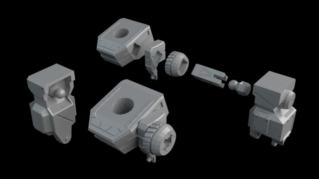
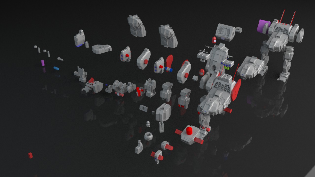
You would have a very similar process to what I undertook for the Jenner and atlas if you're using a makerbot.
I document mostly how it's made here, you might find helpful.
http://mwomercs.com/...-sarah-jenners/
in particular, this part:

and

The majority of joints, with the exception of the balljoint above are simple round pegs with little flanges. In addition to designing specifically for the joints, you have to design for the orientation that you're printing in. Or you'll be in for a lot of sanding/filing/hair pulling. Hope this gives you some insight.
This is by no means the 'best' way. I'm more of a 3D artist than I am an engineer type. But this is the way I found worked for me at this scale with my printer (which is similar to the replicator in many ways) As kiriage has said, It'd be cool to see what you come up with from a CAD type of perspective.
Edited by Valcrow, 07 November 2013 - 09:22 PM.
#4
Posted 08 November 2013 - 12:23 PM
Danke Valcrow and Kiriage! I have seen your work Valcrow and am agog over it. It is really impressive and inspiring/demotivating (lulz).
TL/DR: I have a netric sewage-ton of work to do, but it should be interesting and produce some badass and unique gifts and goodies.
Valcrow, I already know my scale will be smaller than your jenners, primarily out of issues with print time constraints. It is not likely that the department will let me tie up the machines for a 20 hour print for a toy.
The plan, as it stands, is to write a proposal for a project which culminates with the printing of the model. The program I am working on is a manufacturing drafting certificate and detailed plans with tolerances would be a must for it to be received well by the department heads. I had not really thought about varying tolerances of machines, even after having read Valcrow's excellent post How its made:3d-PSJ with its details on the revision process.
The replicator 2 prints at a 100 micron layer height and I am unaware of its tolerances off the top of my head. An additional consideration (given time investment) with this project is that I will personally own a Prusa i3 (most likely the makerfarm kit) by the end of January. This model prints at .50 MLH resolution. So many stupid questions about tolerances here, yay reading in my future.
Most likely the project will be completed in solidworks or autodesk fusion 360 (free to students/entrepeneurs/hobbyists) with technical drafts handled in autocad 2014. Christmas this year for a few of my friends will be a technical readout style poster from the school plotter.
The last frustration is that I amworking on 13 credit hours this term, and 14 credit hours the two following. I have to be time economical with how much hobby learning I am doing, lest I let my grades slip(RHOD participation pretty much got the guillotine with the start of the term, but I made a few matches at least). The 3d course work (solidworks and autocad inventor) will be covered in the winter and spring term and a lot of the actual modeling work is likely to pushed off till then. (Apprenticed in 2D cad for cabinetry and framing, am a n00b to full 3d manip beyond google sketchup).
I guess I should start a thread outlining some of the ground I covered in terms of getting geometry into autocad 2014. One of the teachers in my program is actually a black box tester for fusion 360 at the Autodesk office in Portland Oregon. The software is cloud based and highly geared towards collaboration, ease of use and design facilitation. While visiting the Autodesk offices for a tour last week I had a chance to pick his brain and he mentioned a few tools that sound interesting. Primarily a surface wrapping technique which will form to non-Autodesk geometry to create solids. (If you are ever in Portland, Or. call the Autodesk office and see if the gallery is open, it is pretty killer and public-ish. There is one in san fran as well, if I remember correctly.)
Thanks for the advice, back to the drawing board (which has a much less defeatist meaning for me these days).
#5
Posted 08 November 2013 - 01:12 PM
Very cool, I'm sure you'll learn quite a bit undergoing the process, I know I did.
If you're using game models, you may not need to model much which may save you a lot of time. However, you will have to fix the model, and that might not be so good in solidworks because they're polybased models with holes and double faces everywhere. Might want to try a small piece first before committing to it. i've never used solidworks, but I don't think its super friendly for that process.
If you're considering tolerances, keep in mind that these FDM printers don't have a fixed tolerance on all axises. X and Z are usually the same, but Y is different. Because the print head is ~.40 mm usually, you have a maximum resolution of a .40 mm on the X and Z plane, while the Y can be down to 50 microns depending on your printer. (I printed one of the atlas heads at 40microns.) This will play a huge part in orientating your parts since the smallest detail you can obtain on the X and Z are 40.mm. And then you'll have heat and melting issues.
In terms of scale, I wouldn't recommend going too much smaller than the Jenner. the balljoint piece you see is pretty much as small as it can go before running into printer limitations. Especially if tolerance is important to your grades, the larger you can make it, the less trouble you're going to have with the technical limitations of the printer itself and you can focus more on design. You may spend just as much time fudging with the limitations of the printer than you would just printing stuff if you make it too small. I would test with the smallest joint or connection before making the commitment to print the whole thing in that scale.
The prusa looks like a solid pick. Good on you for getting a kit, learning how the thing works by building it piece by piece is the way to go. Makes troubleshooting way less stressful later.
Best of luck!
#6
Posted 08 November 2013 - 03:52 PM
Good tips and thanks again Valcrow
I have come to realize that a poseable Jenner through printing may be a bit out of reach for my first try. It will probably need to be a single print regardless, but it may also be dependent on how much build time/volume I will be able to negotiate for. I started a thread for it though, going over a bit of the decision process in how to pull the model in etc. see it here , will be posting in that thread moving forward.
The downside of autcad is that it is really picky about what can and cannot be an object in its programming. So whereas blender can modify the game model and make it something, autocad pretty much can't. Which, uhm, well, sucks. I figure i will play around with the models some, get a feel for how i want to approach it. I may take advantage of the close ties to Fusion 360 and see if there is not a way to wrap and patch the existing external geometry to get a quick (relative) mid range detail from it.
1 user(s) are reading this topic
0 members, 1 guests, 0 anonymous users


