Power tools + cold medicine= bad combo.

MWO Simulator work log
Started by Foust, Jul 23 2012 07:43 PM
230 replies to this topic
#102
-
-

- Legendary Founder

- 394 posts
Member
- LocationKentucky

Posted 14 September 2012 - 05:18 AM
I did not have alot of time last night but I did get the gimbals pulled out of the stick and started on the hall conversion. After taking it apart it seems like there is some slop in the gimbals. Ill have to add some shims or do something else creative to try to tighten things up.
This is one half of the gimbal prepped for modifications.
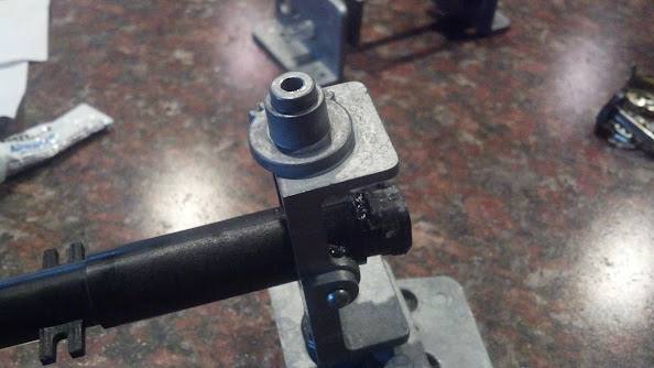
SO MUCH GREASE on these things. Ill have to slime it up again once I'm done.
These are with the hall sensor housings installed (bic pen)
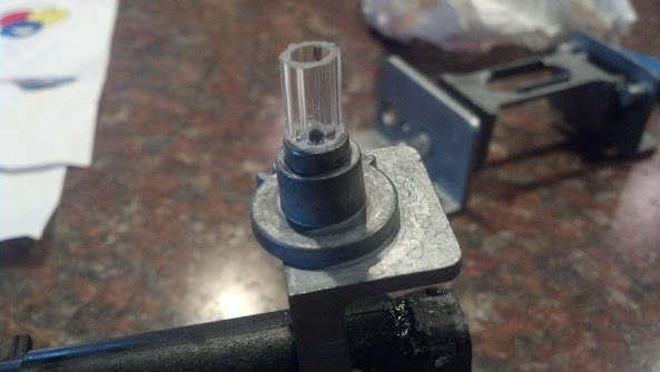
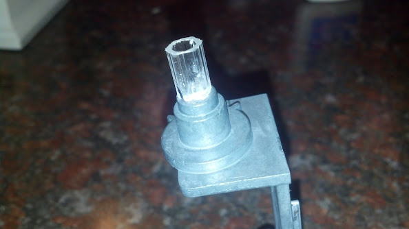
Assemblies back together, with magnets glued in place.
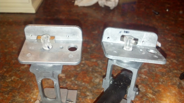
And now mounted back into the base.
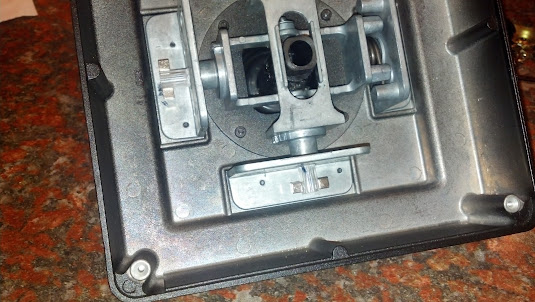
Next up is devising and attaching a mount to align the halls in the housing and wire it up for testing the axis.
This is one half of the gimbal prepped for modifications.
SO MUCH GREASE on these things. Ill have to slime it up again once I'm done.
These are with the hall sensor housings installed (bic pen)
Assemblies back together, with magnets glued in place.
And now mounted back into the base.
Next up is devising and attaching a mount to align the halls in the housing and wire it up for testing the axis.
#103
-
-
- Legendary Founder
- 394 posts
Member
- LocationKentucky
Posted 16 September 2012 - 06:03 PM
Got some work done on the pod this weekend.
This is the door mostly skinned and trimmed.
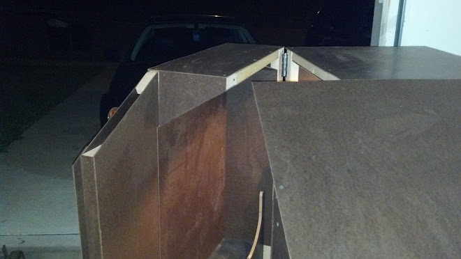
Another shot of the door. You can see here how much room you have to actually get into the pod. I have been in and out of it countless times and have yet to hit my head.

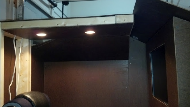
I got the standard lighting put in as well. You can see I don't have the panel in behind the seat yet. I determined that the most central place to run all my controls to was right under the seat. Ill then run the external connections out through the back panel.
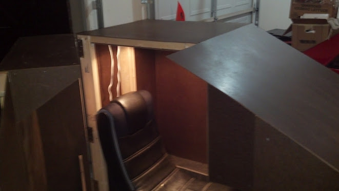
This is a shot with the door at about 90 degrees open, looking at the inside.

I still have to do more paneling and trim work, and I have to build the control mounts. I wont even get into the rest of the list that seems to grow after each thing I complete. And that list is just functional elements, I have not yet begun to paint and detail...
Anyone have a good source for a hula girl?
This is the door mostly skinned and trimmed.
Another shot of the door. You can see here how much room you have to actually get into the pod. I have been in and out of it countless times and have yet to hit my head.
I got the standard lighting put in as well. You can see I don't have the panel in behind the seat yet. I determined that the most central place to run all my controls to was right under the seat. Ill then run the external connections out through the back panel.
This is a shot with the door at about 90 degrees open, looking at the inside.
I still have to do more paneling and trim work, and I have to build the control mounts. I wont even get into the rest of the list that seems to grow after each thing I complete. And that list is just functional elements, I have not yet begun to paint and detail...
Anyone have a good source for a hula girl?
#104
-
-
- Ace Of Spades
- 522 posts
Member
- LocationNew Zealand
Posted 17 September 2012 - 01:45 AM
I hadn't seen your thread previously Foust, so nice to see some recent work getting getting your thread bumped. Also cool to see the variety of people's work matches the variety of all the different 'mechs out there.
#105
-
-
- Legendary Founder
- 394 posts
Member
- LocationKentucky
Posted 18 September 2012 - 08:37 AM
Because I got started after the kids bed time I went back to the quiet(er) work of rewiring the joystick.
I have seen several implementations of halls on a rotational axis, so I attempted to copy that.
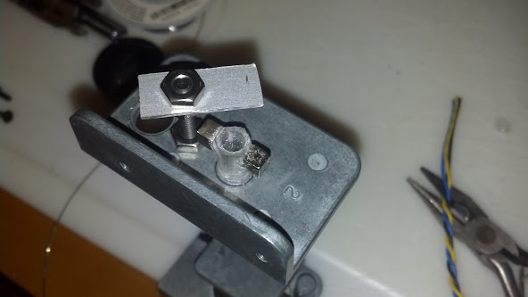
So that worked out well, once I gave up on trying to cut and drill the perf board, that seemed to either shatter when I took the coping saw to it or shatter once I took the drill to it... That is why you see the aluminum bar.
So I get that all together and then drop it into the base. It does not fit. Crap.
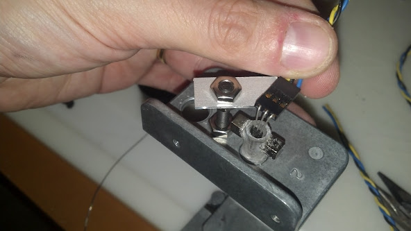
This is what I should have done from the beginning proving yet again that simple is better.
Yes I did just hot glue that in place. Thankfully I used hot glue instead of epoxy, because when I tested the axis up was down and left was right. So I peeled the x axis up, bent the hall the other way and flipped it over. I play with Y inverted so I left that one alone.
It can not be over stated how awesome seeing a dead stable set of axis is. ZERO float.
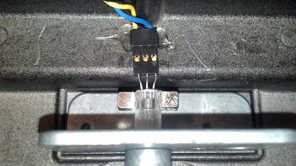
Here I label the axis wires so I don't mis wire them later when I add them to the outbound wire bundle.

I kept going back and forth on do I want to make this just the HOTAS+Rudders or the MechSim as a whole. I decided to go with the MechSim as a whole. I will be running the triggers and individual push buttons as standalone buttons and run the hat switches as part of the 64 button matrix. This means that I passed 24 wires through the base to the handle (3 Cat5 Bundles), and will use 17 I think. (Missing my black book at work) I will pick up the axis wires in the base and pass them out on the 3 cat5 cables. 20 of the 24 wires available. Leaves room for either replacement or repair.
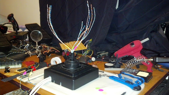
I cut a section of perf board to wire the in handle matrix, which means I only send 10 wires out for the 4 hat switches instead of the 32 it would take for the 16 individual switches in the hats. I attached half of the stick to the base and got to wiring.
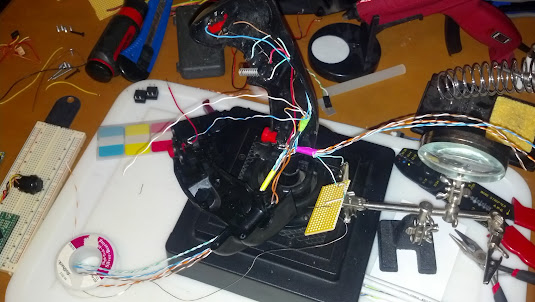
I got all the push buttons wired and started on the matrix. I stopped shortly after that because wiring on non copper clad perf board is a real PITA. I need to develop a better strategy for that.
Also I have no idea what I am going to use 4 hats on this stick for. But darn it they will work if I figure out a use for them.
I have seen several implementations of halls on a rotational axis, so I attempted to copy that.
So that worked out well, once I gave up on trying to cut and drill the perf board, that seemed to either shatter when I took the coping saw to it or shatter once I took the drill to it... That is why you see the aluminum bar.
So I get that all together and then drop it into the base. It does not fit. Crap.
This is what I should have done from the beginning proving yet again that simple is better.
Yes I did just hot glue that in place. Thankfully I used hot glue instead of epoxy, because when I tested the axis up was down and left was right. So I peeled the x axis up, bent the hall the other way and flipped it over. I play with Y inverted so I left that one alone.
It can not be over stated how awesome seeing a dead stable set of axis is. ZERO float.
Here I label the axis wires so I don't mis wire them later when I add them to the outbound wire bundle.
I kept going back and forth on do I want to make this just the HOTAS+Rudders or the MechSim as a whole. I decided to go with the MechSim as a whole. I will be running the triggers and individual push buttons as standalone buttons and run the hat switches as part of the 64 button matrix. This means that I passed 24 wires through the base to the handle (3 Cat5 Bundles), and will use 17 I think. (Missing my black book at work) I will pick up the axis wires in the base and pass them out on the 3 cat5 cables. 20 of the 24 wires available. Leaves room for either replacement or repair.
I cut a section of perf board to wire the in handle matrix, which means I only send 10 wires out for the 4 hat switches instead of the 32 it would take for the 16 individual switches in the hats. I attached half of the stick to the base and got to wiring.
I got all the push buttons wired and started on the matrix. I stopped shortly after that because wiring on non copper clad perf board is a real PITA. I need to develop a better strategy for that.
Also I have no idea what I am going to use 4 hats on this stick for. But darn it they will work if I figure out a use for them.
#106
-

- 6 posts
Rookie

Posted 18 September 2012 - 08:55 AM
I like the sim cockpit but only a single screen? What happens when they put in triple screen support?
http://www.obutto.co...r3volution.html
I have the original obutto and with the side seat accessories I will be able to mount the HOTAS Warthog.
http://www.obutto.co...r3volution.html
I have the original obutto and with the side seat accessories I will be able to mount the HOTAS Warthog.
#107
-
-
- Legendary Founder
- 394 posts
Member
- LocationKentucky
Posted 18 September 2012 - 09:06 AM
 Marcus Rova, on 18 September 2012 - 08:55 AM, said:
What happens when they put in triple screen support?
What happens if/when I get a bigger screen? I rebuild that area. Same thing if I change my mind about the multiple displays. I know it does not look like it, but I did design this thing to break up into manageable pieces. One of those pieces is the screen mount and the bezel.
It is part of the fun of a DIY pit. It is a ever evolving project.
#108
-
-
- Legendary Founder
- 394 posts
Member
- LocationKentucky
Posted 18 September 2012 - 07:56 PM
Worked on the matrix board that goes in the handle. Doesn't look like much but it took a few hours, cutting and stripping the cat5 with a AWFUL set of strippers.
Also, it is important to note that when you tell your wife you want better strippers that you should indicate that you are referring to wire strippers.
Laying out the rows

This pic is where I stopped for the night, rows set and two columns. One hat wired in. I have to rewire each hat as well since they were set for common ground.
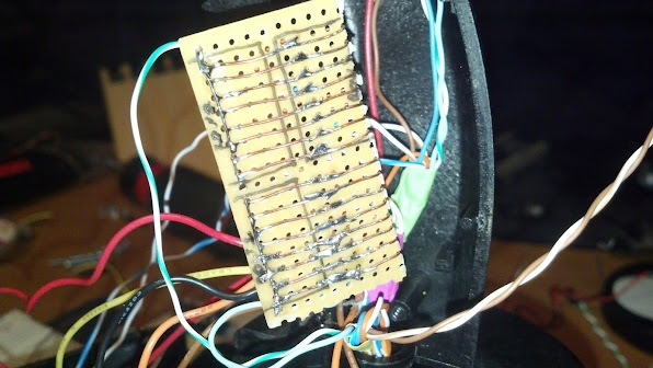
I need to pick up a better set of (wire) strippers and some flush cut snips. I have to clean up the traces I built before stuffing this all back together.
Also, it is important to note that when you tell your wife you want better strippers that you should indicate that you are referring to wire strippers.
Laying out the rows
This pic is where I stopped for the night, rows set and two columns. One hat wired in. I have to rewire each hat as well since they were set for common ground.
I need to pick up a better set of (wire) strippers and some flush cut snips. I have to clean up the traces I built before stuffing this all back together.
#109
-
-
- Legendary Founder
- 394 posts
Member
- LocationKentucky
Posted 27 September 2012 - 06:08 AM
So shame on me more work done less pictures. More trim in the pit (will that ever end?), built one of the lower panel mounts and added a panel to it.
That is really really cool by the way, sitting in the pit flipping toggles, making power up noises, watching your wife roll her eyes....
Any way, I got the matrix cleaned up for the stick and managed to get it all closed up. It was while I was tightening the last screw on the stick that I got that sick feeling in the pit of my stomach. I had mounted the stick backwards. Cursing I open the thing back up, reroute and rewire a few pinches I found turn the stick around and close it back up again.
Here is the cleaned up matrix.
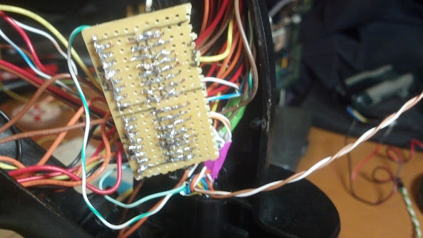
Here is the stick about to be closed up backwards....
Now here is the big shame on me part. I opened up the throttle and mapped out the wires. I pulled out the "Mouse" that was in the thing, took one look at it and decided that I wasn't going to screw with it. So what I did was pull a joystick out of a old xbox controller and wired it up. It fit fairly well. Nothing some hot glue couldn't fix. I cursed some more putting that all back together. Then I realized I didn't take any pictures of any of this process, but it was pretty straight forward.
At any rate I at least snapped a picture of the half mounted stick with the little eraser nub on it.

This is probably the extent of the work I'm going to get done this week unless I take this stuff with me to the conference I am attending this weekend. However the wife is very interested in getting that garage bay back so the project priority might shift.
That is really really cool by the way, sitting in the pit flipping toggles, making power up noises, watching your wife roll her eyes....
Any way, I got the matrix cleaned up for the stick and managed to get it all closed up. It was while I was tightening the last screw on the stick that I got that sick feeling in the pit of my stomach. I had mounted the stick backwards. Cursing I open the thing back up, reroute and rewire a few pinches I found turn the stick around and close it back up again.
Here is the cleaned up matrix.
Here is the stick about to be closed up backwards....
Now here is the big shame on me part. I opened up the throttle and mapped out the wires. I pulled out the "Mouse" that was in the thing, took one look at it and decided that I wasn't going to screw with it. So what I did was pull a joystick out of a old xbox controller and wired it up. It fit fairly well. Nothing some hot glue couldn't fix. I cursed some more putting that all back together. Then I realized I didn't take any pictures of any of this process, but it was pretty straight forward.
At any rate I at least snapped a picture of the half mounted stick with the little eraser nub on it.
This is probably the extent of the work I'm going to get done this week unless I take this stuff with me to the conference I am attending this weekend. However the wife is very interested in getting that garage bay back so the project priority might shift.
#110
-
-
- Legendary Founder
- 394 posts
Member
- LocationKentucky
Posted 01 October 2012 - 05:37 AM
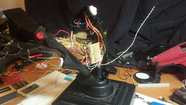
Did some wiring yesterday afternoon.
Some pictures from the throttle wiring.

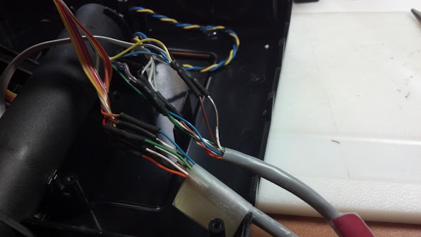
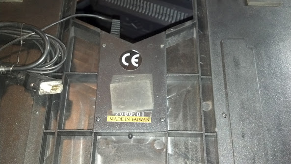
Putting in the hall sensor
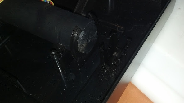

I noticed before I tore this thing down that the detents for idle and mil were barely noticeable. When i got it open, the problem was that the notches on the shaft were worn down. So I could either try to build them back up, or shim the spring.
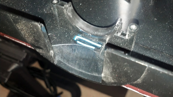
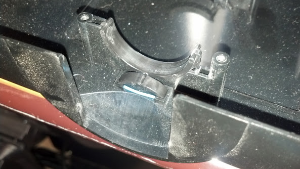
Put it all back together, and I may have put to big a shim in there. The throttle action is a bit stiffer than I like, but you can feel the idle and mil detents now.
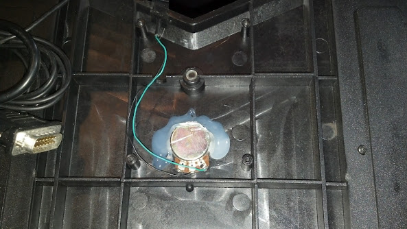
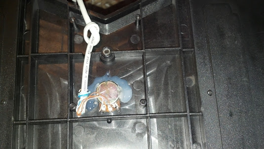
Next onto the rudders. I ran out of hall sensors and I did not want to wait, so I'm HOPING that the pot in there isn't totally shot. I have to say though, even if it is it won't take me long to rebuild it with a hall.
Cover on
Cover off
Rewired
After I buttoned these up and added some wire dressing, I started in on the matrix board. This is stupidly tedious work since I'm trying to be cheap about it. Once I finish that up I can start getting all the pieces together. The wife is getting anxious to get the pit out of the garage so she can get her van in it so I might be able to devote some more time to it.
The pit still needs a panel mount for the door side and the overhead, (surprise) more trim work, door handles and paint. I still have to get my relay controlled outlets built, break my rule about not having 110v at the panels or replace my lighting with 12v LEDs. More work to go with LEDS, more cost for relay controlled, potential hazard with 110 at the panel....
Fast, Cheap, Right. You get to pick two.
Some pictures from the throttle wiring.
Putting in the hall sensor
I noticed before I tore this thing down that the detents for idle and mil were barely noticeable. When i got it open, the problem was that the notches on the shaft were worn down. So I could either try to build them back up, or shim the spring.
Put it all back together, and I may have put to big a shim in there. The throttle action is a bit stiffer than I like, but you can feel the idle and mil detents now.
Next onto the rudders. I ran out of hall sensors and I did not want to wait, so I'm HOPING that the pot in there isn't totally shot. I have to say though, even if it is it won't take me long to rebuild it with a hall.
Cover on
Cover off
Rewired
After I buttoned these up and added some wire dressing, I started in on the matrix board. This is stupidly tedious work since I'm trying to be cheap about it. Once I finish that up I can start getting all the pieces together. The wife is getting anxious to get the pit out of the garage so she can get her van in it so I might be able to devote some more time to it.
The pit still needs a panel mount for the door side and the overhead, (surprise) more trim work, door handles and paint. I still have to get my relay controlled outlets built, break my rule about not having 110v at the panels or replace my lighting with 12v LEDs. More work to go with LEDS, more cost for relay controlled, potential hazard with 110 at the panel....
Fast, Cheap, Right. You get to pick two.
#111
-
-
- 278 posts
Member
- LocationMichigan
Posted 01 October 2012 - 05:41 AM
Nice work on the controllers Foust.
I too struggled over putting a 110v panel in my pit. Finally I decided to do so, but I am using UL listed boxes, switches etc and I have a master power switch anyway that cuts power to the pit when not in use.
Looking great!
I too struggled over putting a 110v panel in my pit. Finally I decided to do so, but I am using UL listed boxes, switches etc and I have a master power switch anyway that cuts power to the pit when not in use.
Looking great!
#112
-

-
- 609 posts
Member
- LocationSomewhere north of St. Petersburg
Posted 01 October 2012 - 03:37 PM
Regarding the issue of having 110V in the panels, etc. ... if you go that route, I highly recommend putting GFCIs (Ground Fault Circuit Interrupters) [aka GFIs] in those circuits.
For those who may not know how they work... in a nutshell: There are 3 conductors, Hot, Neutral and Ground. 120VAC should be passing all of the current over the Hot and Neutral conductors. That means that both of those legs measure the same amount of current flow. If a fault develops, the Hot and Neutral legs will not have the same current levels, and the GFCI trips (VERY quickly). In other words, if one of your power leads starts to short, that GFCI is going to trip the circuit.
Now, what that scheme will not protect you from, is grabbing on to the Hot lead with one hand, and the Neutral with the other, while your body is insulated from ground. That would just make you a power load on the circuit, with no difference in current flow on either leg. The take-away from that is... make sure your pit / pit panels are well grounded.
GFCIs can be obtained in several form factors. 1. A GFCI wall outlet (typically seen in bathrooms). 2. A GFCI breaker for your breaker panel. 3. A GFCI extension cord.
Cheers, and be safe!
Edited by CyBerkut, 01 October 2012 - 03:38 PM.
#113
-

-
- Bridesmaid
- 2,100 posts
Member
- LocationTerra
Posted 01 October 2012 - 04:29 PM
Foust, on 08 September 2012 - 04:24 PM, said:
This is the matrix board in the handle, I really wish I knew what they were doing with this cause they are only taking 5 wires through the handle. My current plan is 23ish. Ill have to consult the book.
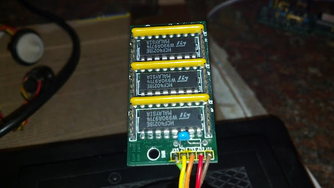
Might be a bit late, but here goes... thoose chips are labeled as 4021, which is a generic IC identifier. They're 8bit shift registers. So, basically, what gets done is that the input from the buttons goes into the chip, is saved and then pulsed out one by one. Looks like the 3 chips are in series to get 24 bit output. The 5 wires are probably GND, VCC, parallell/serial select, clock and data.
For a more detailed explanation, I'd recommend reading the datasheet of the 4021, available e.g. here: http://www.classiccm...ric-number.html
or
http://en.wikipedia....grated_circuits
Unlike you want to build a circuit for deserialising the data (or extend the program of the teensy with a routine which does that), you're probably better off running the buttons directly into the teensy/building your own matrix.
Edited by Exilyth, 01 October 2012 - 04:40 PM.
#114
-
-
- Legendary Founder
- 394 posts
Member
- LocationKentucky
Posted 03 October 2012 - 08:01 AM
Exilyth, on 01 October 2012 - 04:29 PM, said:
Unlike you want to build a circuit for deserialising the data (or extend the program of the teensy with a routine which does that), you're probably better off running the buttons directly into the teensy/building your own matrix.
My thoughts exactly. :-)
#115
-
-
- 2,299 posts
Member
Posted 03 October 2012 - 04:47 PM
It's nice to see some people still go the DIY route!
It's a good thing I'm too poor to do this. My goodness, I would have no life ...
----
FOUST:
Have you seen the pictures I have linked to in this post and their descriptions?
http://mwomercs.com/...y-an-education/
Now if only you could do it with a collimated display in a cockpit suspended in a fully actuated triple-ring setup on a rotating arm ... hehehe.
#116
-
-
- Legendary Founder
- 394 posts
Member
- LocationKentucky
Posted 08 October 2012 - 05:28 PM
Small update.
I finished all of the trim (that I know of). Cut the holes and mount points out for the intake and exhaust fans. FORGOT to cut the back connector plate out. Glued the mounting ears to the overhead panel. Oh and as I type this, I still have to put in handles. Forgot about that to....
I plan on using some paint-able caulking to "fix" some of my less than stellar joinery and with any luck should be able to move on to painting and perhaps relocating the pit by this weekend. Then there is nothing left to do but wire.
And wire.
and wire.
I have a lot of wiring to do....
#117
-
-
- 278 posts
Member
- LocationMichigan
Posted 08 October 2012 - 05:30 PM
Keep it up Foust, we are all looking forward to picture updates.
#118
-
-
- Legendary Founder
- 394 posts
Member
- LocationKentucky
Posted 23 October 2012 - 06:12 AM
I've been hesitant to post progress without pictures, but hey this is my work log right? I'm not here for your (desperately needed) approval. This is to keep track of what I've done. Right?
So after underestimating how much paint it would take to cover the thing and another trip out to get paint, I have it covered in a nice shade of dark grey called "Knights Armor". I would be lying if I said the name did not have any influence on the color choice.
Last night the wife and I carried three of the four pieces up the pits new home, my "office". We left the last one because it ended up being much heavier than I thought it was going to be and I didn't want to hurt my wife or myself in the process of moving it. I will be borrowing a dolly tonight and hopefully getting it moved.
Is it acceptable that I haven't got the thing finished yet and already want to do major revisions? TurboCorvair's pit revisions are awesome and I REALLY want to emulate his work. It is simply superb.
I swear once its in place in and reassembled in the office Ill get some more pictures.
Edited by Foust, 23 October 2012 - 07:11 AM.
#119
-
-
- Elite Founder
- 822 posts
Member
Posted 28 October 2012 - 09:50 AM
wow, that is great man, no worries, this monday = open beta 
#120
-
-
- Legendary Founder
- 394 posts
Member
- LocationKentucky
Posted 08 November 2012 - 06:10 AM
Update time now with more pictures!
Not of the pit, but of the controllers.
This is the socket for the Teensy++ with all of the connections out to the 8 port patch panel. The joystick takes up 3 ports, the throttle 2 and the rudder 1. The remaining 2 ports go out to the matrix board.
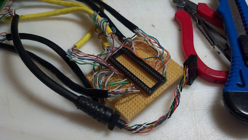

I had no project boxes available and I didn't want to wait for one so I built a enclosure. Quick and dirty from scrap material.
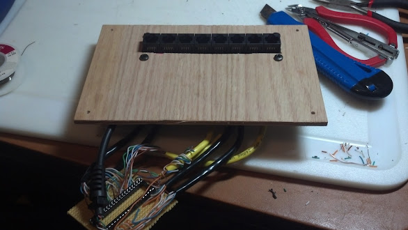
I hacked up a back plate usb connector from a old PC build to add the usb mini instead of the pin header end to put a port on the outside of the box.
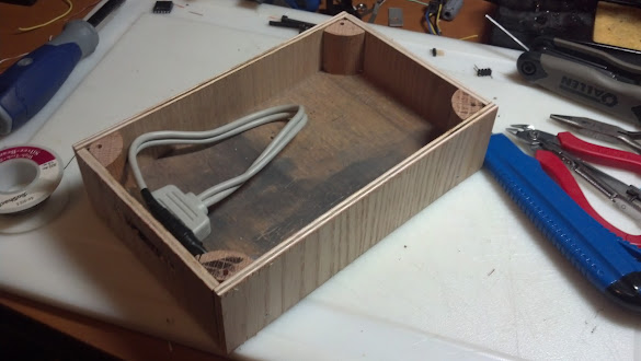

To make this work I had to make an A to A cable to go between the control box and the PC.

Here they are all plugged in and working!
Remember earlier when I said that the axis were reversed? Up was down. Left was Right. Remember how I said that I flipped X? Then remember how I said I put the stick on backwards?
Yeah so I need to flip X again.
To the mechpit. I went man mode the other day and brute forced the thing up the stairs. It was not pretty, but it is now in place. I dont have pictures of it in place because its still in "wiring mode" meaning that alot of the panels are off to route wire.
Now that its in place and I'm putting things inside, I'm redesigning it in my head. In part I blame TurboCorvair because what he is doing I want to do. However my pit was not laid out to accommodate that design decision.
Specifically I am not very happy with the display area. It desperately needs a console in front of it and I really want to put in a larger screen. I am considering using the three 21's I have in portrait. Mainly because I don't have the width in the mechpit to put them in landscape.
Decisions decisions. And build time...
Not of the pit, but of the controllers.
This is the socket for the Teensy++ with all of the connections out to the 8 port patch panel. The joystick takes up 3 ports, the throttle 2 and the rudder 1. The remaining 2 ports go out to the matrix board.
I had no project boxes available and I didn't want to wait for one so I built a enclosure. Quick and dirty from scrap material.
I hacked up a back plate usb connector from a old PC build to add the usb mini instead of the pin header end to put a port on the outside of the box.
To make this work I had to make an A to A cable to go between the control box and the PC.
Here they are all plugged in and working!
Remember earlier when I said that the axis were reversed? Up was down. Left was Right. Remember how I said that I flipped X? Then remember how I said I put the stick on backwards?
Yeah so I need to flip X again.
To the mechpit. I went man mode the other day and brute forced the thing up the stairs. It was not pretty, but it is now in place. I dont have pictures of it in place because its still in "wiring mode" meaning that alot of the panels are off to route wire.
Now that its in place and I'm putting things inside, I'm redesigning it in my head. In part I blame TurboCorvair because what he is doing I want to do. However my pit was not laid out to accommodate that design decision.
Specifically I am not very happy with the display area. It desperately needs a console in front of it and I really want to put in a larger screen. I am considering using the three 21's I have in portrait. Mainly because I don't have the width in the mechpit to put them in landscape.
Decisions decisions. And build time...


1 user(s) are reading this topic
0 members, 1 guests, 0 anonymous users


