So here we go.
For the history on my previous two iterations, the log can be found HERE.
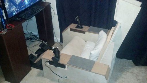
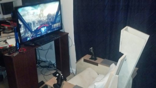
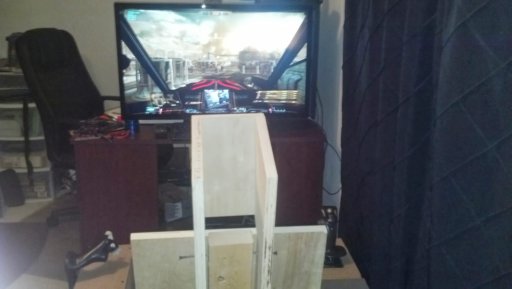
Now I want to say that without LocNar's work, I would probably have given up on the mechpit. I have him to thank for the design of the pit, and the encouragement to keep working out the bugs I had in the control scheme for the stick. Thank You LocNar, could not have made this happen without you.
First I will talk about how you take a perfectly good Thrustmaster T16000M, cut it up in to many many pieces and turn it into a full HOTAS + pedals.
You start out with a factory default T16000M.
Then you take the bottom off to get to all those naughty wires:

See all that stuff? The main control board is the one on the left. On the right is simply the board with the other 6 buttons on it. I should mention now that everything on the base is common ground. It was like they wanted me to hack this thing up. Begged me even. Oh you silly joystick, hack you we shall....
Quite literately, I got the hack saw. I'm not kidding, look:


Yes, I am a monster. I promise though, it is all for a good cause. Hacking the center out of the stick allowed me to keep the factory mounting for the gimbal and sensor, so I could switch back to spring centering in the future if I so choose. It also allows it to fit in my side rail.
Which I guess means this is a good time to mention that I modified the gimbal to be a friction joint instead of spring centered. I originally was going to try to fit a set screw of sorts with a fabric brush to press against the top of the bell on the gimbal to provide the friction, but there is not much space to do such a thing and I had come up with another solution to try out.

That white ring was cut out of a plastic template material sold at fabric stores. It rides on the top of the bell and gets sandwiched between the bell and the top of the case. Little bit of Dow33 and we have a winner.
Mostly. It will fail, it is just a question of when. (Probably soon) You can see why here:
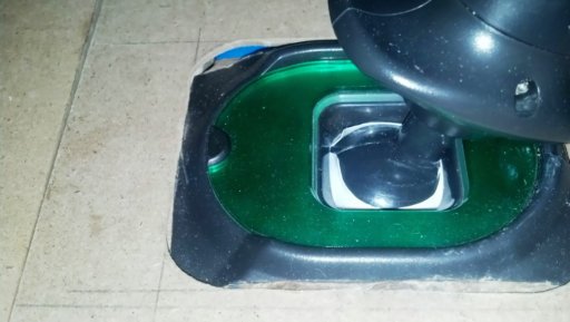
That split will eventually make its way through to the outside of the ring and when that happens it is time to engineer a new solution.
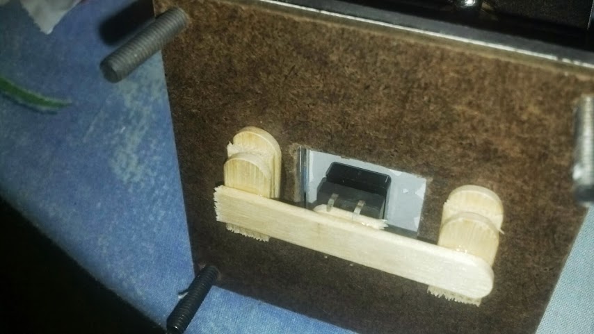
While I had the stick apart to do all that I also removed the spring on the rotation axis of the stick, as well as the pot. I then used tactical popsicle sticks to block the rotation on the stick. Shame on me, no pictures of that.
I mentioned that the wiring was all common ground, here you can see how I tapped into all the switches on the control board side. All of those along with the switches on the right side get sent along the old DB15 cable from the TQS.

This is a shot of what ended up being the mounting of the control board to the bottom of the stick. It is all laid out kind of weird because I was reusing the wire that was in the thing to begin with, and because I needed to be able to fit it into the side rail. I built it such that I could remove the stick and put something else in its place, like a gated shifter. That is a separate project for a later date.
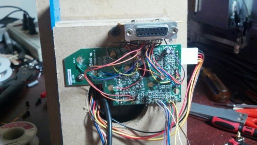
I scavenged that female DB15 from the TQS board as well. Heat guns do wonderful and terrible things to solder. The next image is of the interconnect board I built for the inside of the throttle. I scavenged the pin headers to. I had the shorted pins to show for it to....
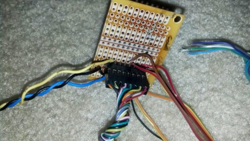
To speak a bit more to the wiring. Outside of taking out the rotational pot from the joystick handle, I left all that alone. I also left the magnet and hall sensor in the gimbal alone. I had planned to use one of my hall sensors from the other stick project to run the throttle.

I was real happy about that arrangement by the way, but it didn't work. My hall sensors work at +5 and the T16000M only runs +3.3 to its pots so that was right out. Remember that pot I just took out of the stick? Yup some hot glue and tactical popsicle stick later and we have a working throttle axis. Thankfully side walls hide the "sins" and tactical popsicle sticks.
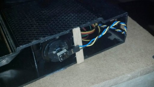
Wired into the main boards throttle axis. Yes it is ugly, yes it works. Don't judge me. The rest of the buttons went to the hat on the throttle, the two two-way toggles and the push button. I have three more buttons available if I come up with a use for them later on.
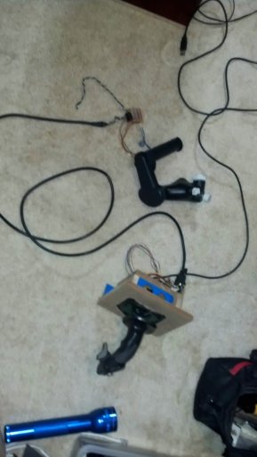
Here is a example of one of my "testing environments" I think this was when I was playing "find the short" and "why wont this axis work.
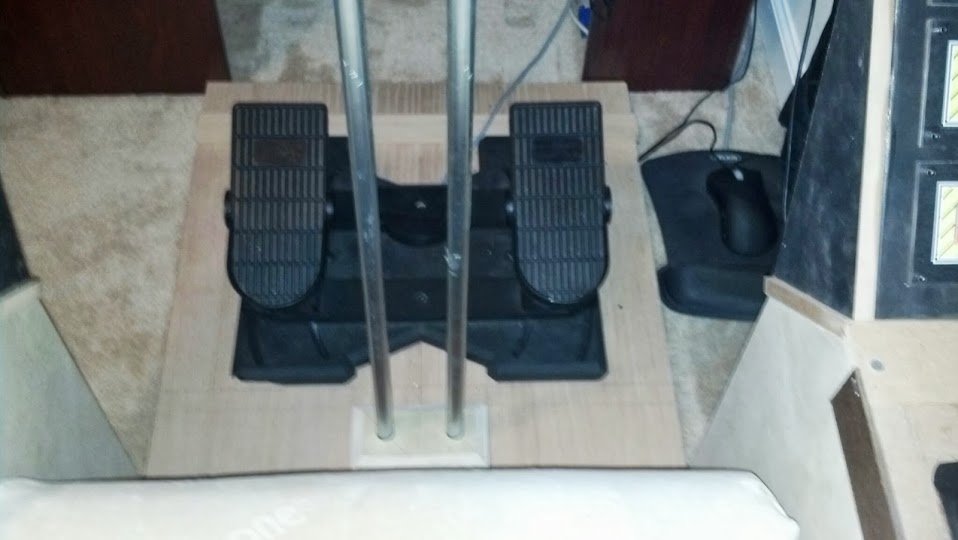
There is not much to say about the rudder pedals. I used the pot that was in them, and wired it to the rotational axis on the main board. Easy.
Im getting nervous about the length of this post, so Ill break here and write up the mechpit itself next.
Edited by Foust, 09 September 2013 - 06:29 PM.


