Jump to content

Catapult 3D Model Breakdown


21 replies to this topic

#1 Horned Owl

    Member

  • PipPip
  • Legendary Founder
  • Legendary Founder
  • 28 posts
  • LocationChicago, IL

Posted 29 September 2013 - 09:26 PM

Just a small 3D model breakdown of the Catapult model from MWO. I thought it would be cool to see an exploded view of a game model seeing as how there were so many elements. After rendering it out, thought it was cool enough to share. Added the wire frame and textures for fun.


Enjoy

Edited to add link for Part 2 as requested.


Edited by Horned Owl, 01 October 2013 - 03:18 PM.


#2 Jin Ma

    Member

  • PipPipPipPipPipPipPipPip
  • 1,323 posts

Posted 29 September 2013 - 09:33 PM

1440p good lord

I CAN HEAR THE PIXELS

so the actual Catapult model has a wider cockpit. do you know what technique they use to narrow it to look like the ingame version?

Is it some kind of distortion effect they apply to the model, so they don't have to go back and remodel all the pieces to be the correct size?

Edited by Jin Ma, 29 September 2013 - 09:35 PM.


#3 sgt scout

    Member

  • PipPipPipPipPip
  • 117 posts
  • LocationLondon

Posted 29 September 2013 - 09:49 PM

Wait ..... whaaaaaaaaaaaat ?

When you seperated it are they all the different meshes in the caterpult ?????????

Is it not made out of a single mesh ????????????????

is that the fully optimised model ??????

If yes is the answear to all those questions i think we may have found why the game is so intensive.
Would love a reply, im studying game animation and modeling and will be starting my final year soon. Im trying to optimise a complex model and have to figure out what i could do with modeling and/or bump maps in order to get it highly detailed and as optimised as possible.

#4 ThunderHorse

    Member

  • PipPipPip
  • Caladbolg
  • Caladbolg
  • 83 posts
  • LocationLas Vegas, Nevada

Posted 29 September 2013 - 09:52 PM

Niiiice. Perhaps you can slow the turnaround or animation effects during some of the exploded animations. It's really interesting to see how the polys all fit together.

#5 Horned Owl

    Member

  • PipPip
  • Legendary Founder
  • Legendary Founder
  • 28 posts
  • LocationChicago, IL

Posted 29 September 2013 - 09:58 PM

Sgt Scout,

This is the model used in game, and yes, it is made up of 416 individual elements, it is NOT one single mesh. This modeling technique helps cut down on polys, modeling time and unwrapping. It is common practice for many game modelers like myself and you.

One solid mesh, or one model made of 416 separate pieces, doesn't matter as far as game performance. What makes that difference is the poly count and texture resolution.

#6 GoodGoblin

    Rookie

  • FP Veteran - Beta 2
  • FP Veteran - Beta 2
  • 4 posts
  • LocationTucson, AZ

Posted 29 September 2013 - 10:38 PM

View PostHorned Owl, on 29 September 2013 - 09:58 PM, said:

Sgt Scout,

This is the model used in game, and yes, it is made up of 416 individual elements, it is NOT one single mesh. This modeling technique helps cut down on polys, modeling time and unwrapping. It is common practice for many game modelers like myself and you.

One solid mesh, or one model made of 416 separate pieces, doesn't matter as far as game performance. What makes that difference is the poly count and texture resolution.


As someone who has studied pretty exentensively in this field along with putting severals models into game engines to test them out, what Horned Owl says is correct. It would be a big waste of time and resources to make a mechanical model all one mesh. It would most likely skyrocket the polycount in areas of large flat polygons to the areas that have small curved details. Not to mention mention the extra time spent unwrapping the uvs to texture. I also would pull my hair out trying to rig a mechanical model all as one mesh. So much easier to select seperate meshes and attach it to a joint then trying to skin every vert for each joint.

#7 Cev Lost

    Member

  • PipPip
  • The Widow Maker
  • The Widow Maker
  • 34 posts
  • LocationDS: Command

Posted 29 September 2013 - 10:48 PM

Huh like to know how to get to those models to peek at them

#8 sgt scout

    Member

  • PipPipPipPipPip
  • 117 posts
  • LocationLondon

Posted 29 September 2013 - 11:41 PM

Thanks gents for the quick reply, i am aware of polly count being the end all and be all of optimisation but i would have guessed alot of it would be through normal or bump maps.
The in game models do look great, and i would often rotate the models within the mechlab to get an idea of what was mesh or clever texturing.
This video is excellent and posted at an excellent time. I have just got down most of my base mesh and quickly riged and weighted it to see the freedom of movement it has. I have kept my modeling as simple as possible with an attempt to create most of its complex shapes through bumps and normal maps. I will definatly make another pass over it and add a few more robot bits.

#9 Sparks Murphey

    Member

  • PipPipPipPipPipPipPipPipPip
  • Bridesmaid
  • Bridesmaid
  • 2,953 posts
  • LocationAdelaide, Australia

Posted 30 September 2013 - 05:48 AM

View PostCev Lost, on 29 September 2013 - 10:48 PM, said:

Huh like to know how to get to those models to peek at them

View Postsgt scout, on 29 September 2013 - 11:41 PM, said:

Thanks gents for the quick reply, i am aware of polly count being the end all and be all of optimisation but i would have guessed alot of it would be through normal or bump maps.
The in game models do look great, and i would often rotate the models within the mechlab to get an idea of what was mesh or clever texturing.
This video is excellent and posted at an excellent time. I have just got down most of my base mesh and quickly riged and weighted it to see the freedom of movement it has. I have kept my modeling as simple as possible with an attempt to create most of its complex shapes through bumps and normal maps. I will definatly make another pass over it and add a few more robot bits.

If you guys are interested, Heffay's got a great tutorial on extracting the meshes and textures from the game files here: http://mwomercs.com/...ing-pgis-mechs/

#10 Sparks Murphey

    Member

  • PipPipPipPipPipPipPipPipPip
  • Bridesmaid
  • Bridesmaid
  • 2,953 posts
  • LocationAdelaide, Australia

Posted 30 September 2013 - 05:51 AM

View PostJin Ma, on 29 September 2013 - 09:33 PM, said:

1440p good lord

I CAN HEAR THE PIXELS

so the actual Catapult model has a wider cockpit. do you know what technique they use to narrow it to look like the ingame version?

Is it some kind of distortion effect they apply to the model, so they don't have to go back and remodel all the pieces to be the correct size?

Ghogiel actually figured this one out: the original (depreciated but still in the game files) model of the Catapult has the wide cockpit, while the newer version has a skinnier mesh.

View PostGhogiel, on 20 September 2013 - 08:14 AM, said:
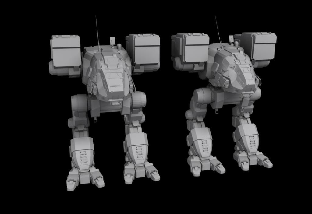
compare here>
Posted Image


#11 Heffay

    Rum Runner

  • PipPipPipPipPipPipPipPipPipPip
  • The Referee
  • The Referee
  • 6,458 posts
  • LocationPHX

Posted 30 September 2013 - 05:56 AM

Horned Owl, how did you do the part where you changed the scale of each of the parts in place while maintaining their relative positions? I'm having an issue with some Star Citizen models where each of the parts are shrunk down in place by about 1000 times, and if I could just scale them up from (I'm guessing) the center of geometry instead of the origin, I could probably get the models to line up a lot better.

#12 Sentinel373

    Member

  • PipPipPipPipPipPip
  • The Money Maker
  • The Money Maker
  • 317 posts

Posted 30 September 2013 - 10:01 AM

View PostVegentius, on 30 September 2013 - 06:43 AM, said:


Field of View.. more commonly known as FOV =]


Actualy it has nothing to do with FOV there are infact 2 models in the game files of the catapult. The scale.cgf model whch has the wide cockpit. And there is the ingame model which is seperated in alot of smaller files and requires you to assemble it from these files yourself. This assembly procces is fairly easy but can be time consuming. Also this video nicely illustrates how many pieces i have to worry about when trying to 3d print one of these models. All those tiny pieces have to be connected if you want to 3d print it

#13 Horned Owl

    Member

  • PipPip
  • Legendary Founder
  • Legendary Founder
  • 28 posts
  • LocationChicago, IL

Posted 30 September 2013 - 12:40 PM

View PostSentinel373, on 30 September 2013 - 10:01 AM, said:

Also this video nicely illustrates how many pieces i have to worry about when trying to 3d print one of these models. All those tiny pieces have to be connected if you want to 3d print it


All the separate pieces do not have to be connected to 3D Print, as long as each separate piece is water tight [(Select Borders: All ---> Cap) works for many, but certainly not all elements].

I had to make my Sarah's Jenner water tight and that certainly took some time as there was plenty of elements that did not simply "Cap solid". So, I fully under stand what you are talking about to make a mech 3D printable. You can see it here if you are not familiar with it: http://mwomercs.com/...-sarahs-jenner/

As far as a slower exploded turnaround, I could certainly render one out. I'll play around with it and get one up as soon as I can. I'll post it on this thread when it's done.

#14 Valcrow

    Member

  • PipPipPipPipPipPip
  • 228 posts
  • LocationCanada

Posted 30 September 2013 - 01:16 PM

View PostHorned Owl, on 30 September 2013 - 12:40 PM, said:

All the separate pieces do not have to be connected to 3D Print, as long as each separate piece is water tight [(Select Borders: All ---> Cap) works for many, but certainly not all elements].


Those uncapped pieces strike fear into my nightmares.

Depends on 3D printers/slicers. Not only watertight, but connected and booleaned into one mesh for my slicer. The catapult was my first mech print, I too used the fat cockpit :/. It is a learning process. :)

#15 Valcrow

    Member

  • PipPipPipPipPipPip
  • 228 posts
  • LocationCanada

Posted 30 September 2013 - 01:22 PM

View PostHeffay, on 30 September 2013 - 05:56 AM, said:

Horned Owl, how did you do the part where you changed the scale of each of the parts in place while maintaining their relative positions? I'm having an issue with some Star Citizen models where each of the parts are shrunk down in place by about 1000 times, and if I could just scale them up from (I'm guessing) the center of geometry instead of the origin, I could probably get the models to line up a lot better.


You can scale on a local pivot, the process depends on the software you're using, but in max, just set your pivot to local. (dropdown beside the scale button) And then click and hold the botton beside that one and go to the 'use pivot point center' option (the one with 2 red dots) And you can scale all objects locally on their own pivots.

Sometimes game models have all the pivots set at the origin though.. in those cases, you can center the pivot on object center, scale them up, and then set the pivot back to origin. (under hierarchy)

#16 Horned Owl

    Member

  • PipPip
  • Legendary Founder
  • Legendary Founder
  • 28 posts
  • LocationChicago, IL

Posted 30 September 2013 - 02:07 PM

View PostValcrow, on 30 September 2013 - 01:16 PM, said:

Depends on 3D printers/slicers. Not only watertight, but connected and booleaned into one mesh for my slicer. The catapult was my first mech print, I too used the fat cockpit :/. It is a learning process. :)


This does not surprise me. Different software has different requirements for the same thing.... kinda the same anyway. For the software I am using, models do not have to be all one mesh nor booleaned together. Overlapping parts of elements are ignored and simply printed solid. Only outside faces are respected for the texture, remember, I am printing in full color with a completely different 3D Printer.

@ Heffay
I did not scale anything to animate the exploded view. I separated each element to it's own object one by one. Then key frame animated each object to achieve the result you see in the video. I simply reversed the process for the re-collapse of the parts into the full Catapult.

#17 Heffay

    Rum Runner

  • PipPipPipPipPipPipPipPipPipPip
  • The Referee
  • The Referee
  • 6,458 posts
  • LocationPHX

Posted 30 September 2013 - 04:58 PM

View PostHorned Owl, on 30 September 2013 - 02:07 PM, said:

@ Heffay
I did not scale anything to animate the exploded view. I separated each element to it's own object one by one. Then key frame animated each object to achieve the result you see in the video. I simply reversed the process for the re-collapse of the parts into the full Catapult.


Ow ow ow ow... you have the patience of a patient guy!

#18 Bishop Steiner

    ForumWarrior

  • PipPipPipPipPipPipPipPipPipPipPipPipPipPipPip
  • The Hammer
  • The Hammer
  • 47,187 posts
  • Locationclimbing Mt Tryhard, one smoldering Meta-Mech corpse at a time

Posted 30 September 2013 - 05:36 PM

ow. Brain hurts.

If this is indicative of the work needed to make a 3D model outta these things..... OW> BRAIN PAIN.

I might be better off trying to whittle one from a chunk of oak, lol.

#19 Bishop Steiner

    ForumWarrior

  • PipPipPipPipPipPipPipPipPipPipPipPipPipPipPip
  • The Hammer
  • The Hammer
  • 47,187 posts
  • Locationclimbing Mt Tryhard, one smoldering Meta-Mech corpse at a time

Posted 30 September 2013 - 07:51 PM

there are FoV setting, in ones user config folder. It is a totally separate thing though from the window size of the Catapult.

#20 Valcrow

    Member

  • PipPipPipPipPipPip
  • 228 posts
  • LocationCanada

Posted 30 September 2013 - 08:52 PM

View PostHorned Owl, on 30 September 2013 - 02:07 PM, said:

@ Heffay
I did not scale anything to animate the exploded view. I separated each element to it's own object one by one. Then key frame animated each object to achieve the result you see in the video. I simply reversed the process for the re-collapse of the parts into the full Catapult.


Yikes, are you using max? There is an explode by angle in Edit mesh to separate all sub-objects by angle into individual separate objects. (so 180 would cause all objects not connected by polys to break apart)


4 user(s) are reading this topic

0 members, 4 guests, 0 anonymous users